Rolls Royce Aero Engine Blisk Weld Fixture
Building on previously supplied successful and innovative fixture and mandrel solutions supplied to RR manufacturing plants located at Derby and Sunderland in the UK, PTG were contacted and asked to look at the feasibility of supplying two new high specification weld fixtures. The first one to improve the Trent 1000’s weld production time and improve engine fuel efficiency, and the second to provide similar benefits for a development engine ( XWB) to be installed on the new Airbus A350 aircraft currently under construction.
The major difference between this fixture design and older fixture designs (non PTG) were two fold:
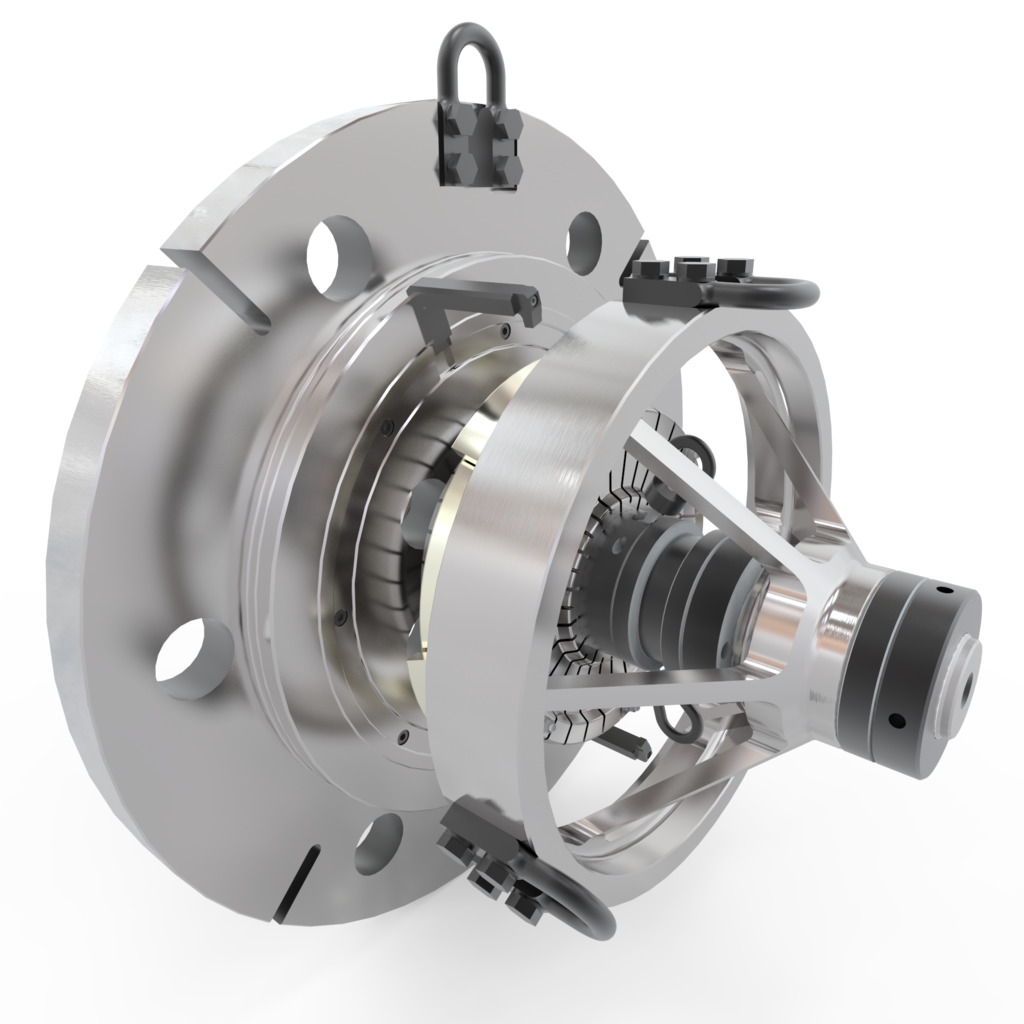
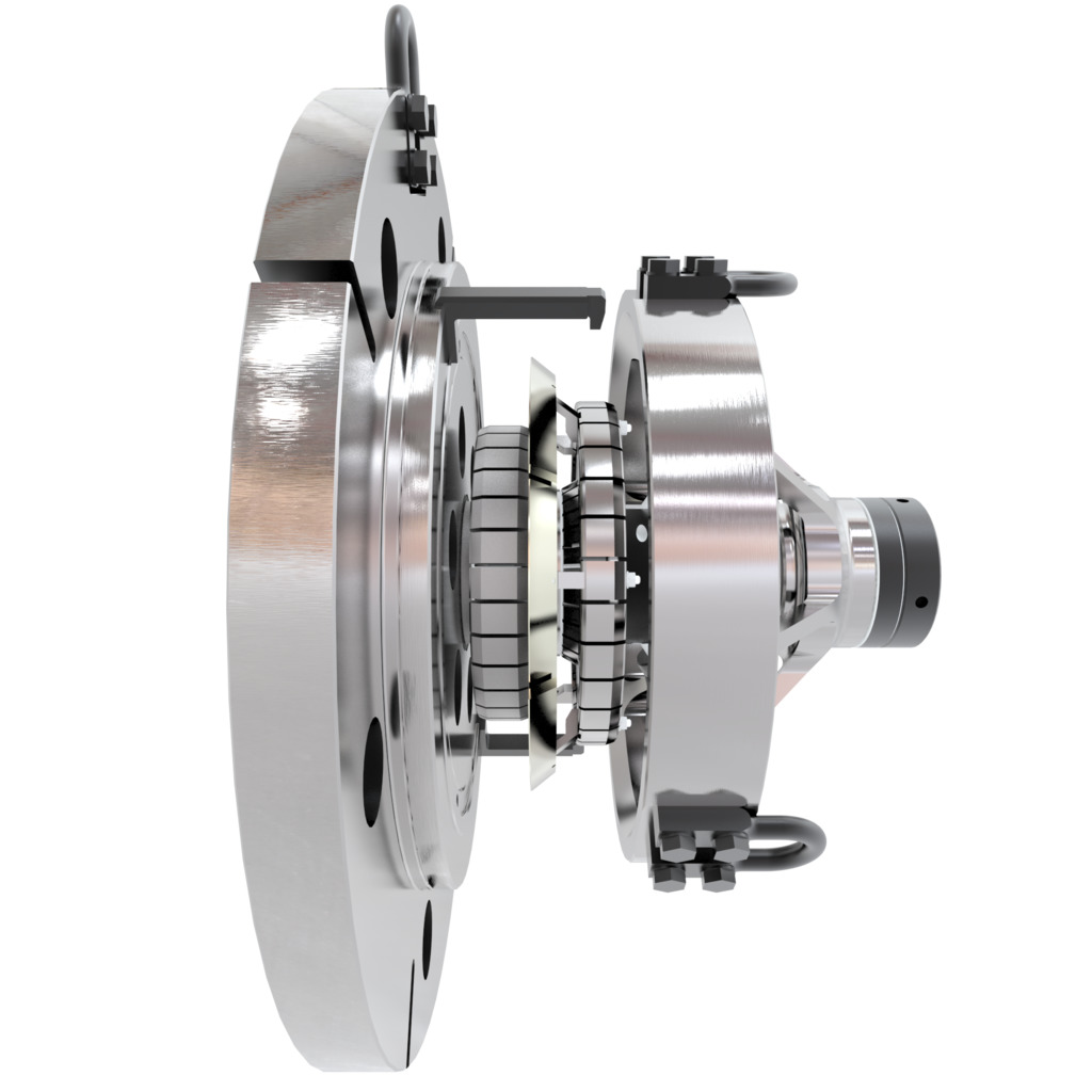
- The fixture would feature a large mandrel with several sleeves to centralise and clamp the turbine disk components together never before utilised.
- One of the components (on fixture two) would be in a finished state and could not be marked in any way or allowed to have any weld splatter from the Electron beam Welding machine reach the finished blisk
The transfer of information took place over several visits by the PTG technical engineering staff until after consultations with the Rolls Royce mechanical engineers a workable solution was reached.
The first problem was to prevent the electron beam, when welding, after penetrating the components to be welded, continuing to strike the fixture.
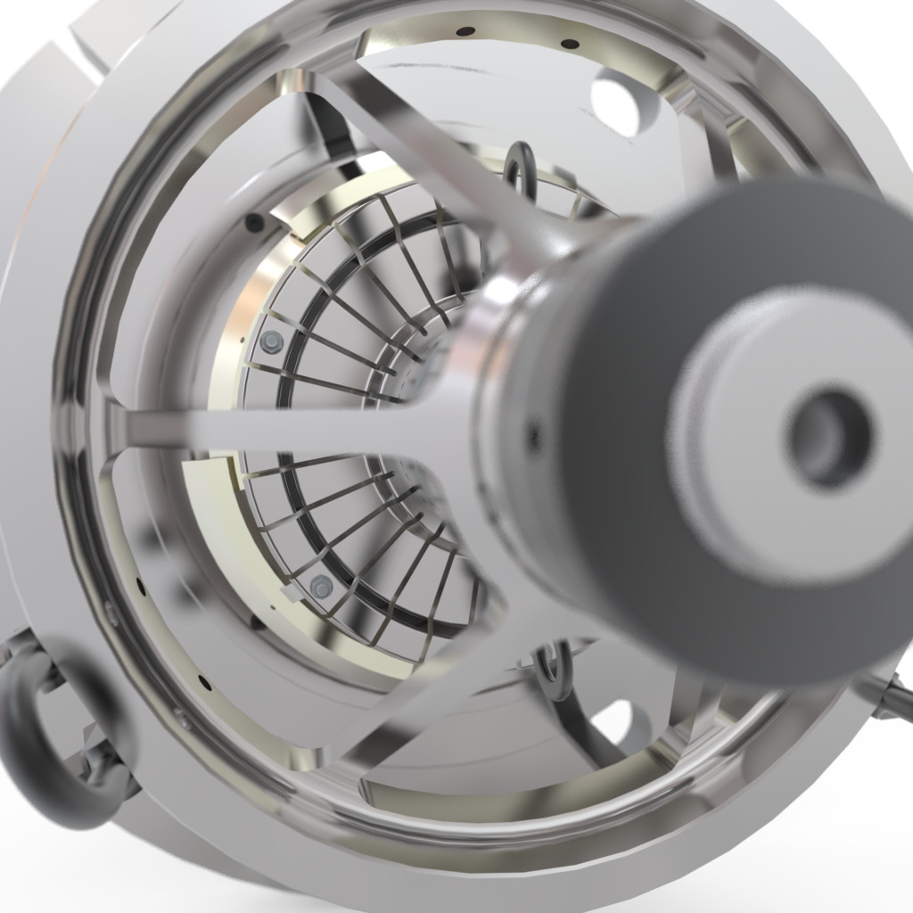
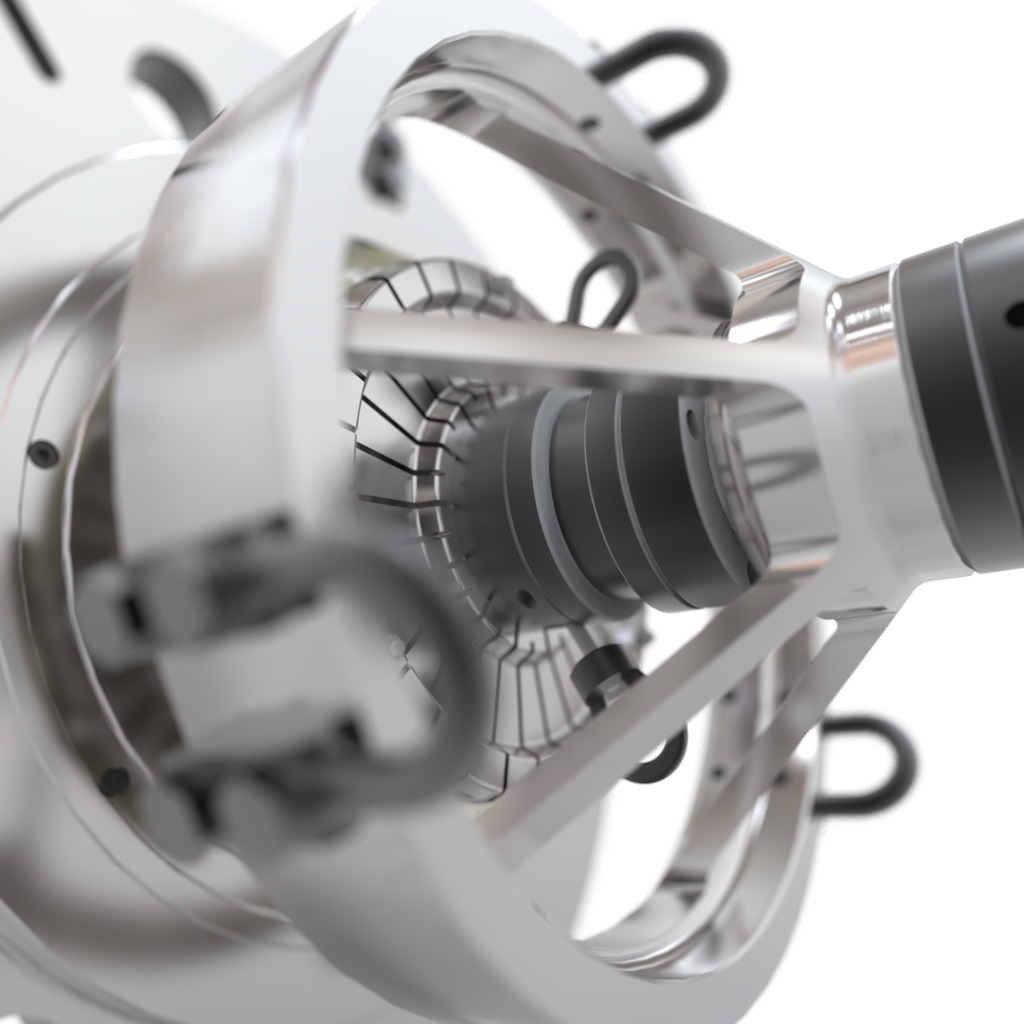
The solution was to locate around and between the sleeves of the mandrel Nickel weld shields; these would move into place as the mandrel fixture was energised, the Nickel shield would be directly in line with the weld and impinge the beam flow further.
Secondly during the welding process the components overall length would contract as the material is displaced, a spring solution was devised to ensure the end clamp remained in place applying pressure to the components throughout the process.
Thirdly, the now welded components had to be withdrawn from the fixtures without dismantling the fixtures, a solution to this problem was found utilising ground spacers to reposition the actuation feature of the mandrel sleeves.
Finally how were the weld engineers going to load the components?
The loading method was to locate a specially designed lifting attachment in the bore of the component, this was now to present a problem as the bore was being used by the sleeves for location, the solution was to profile grind the sleeves and provide a specialist lifting device for the components.
The company have now purchased six of the lifters to be used in different parts of the rotatives business.
With the initial design problems now overcome and the design and 3D model supplied accepted and signed off for both fixtures manufacturing commenced.
After delivery the benefits of both fixtures were apparent from the day of first use.
The fixtures could be loaded with the three individual turbine discs and clamped in position in a matter of minutes as no “clocking up” of each individual disc was required prior to clamping.
This advantage alone saved the operators approximately 2.5 hours of loading time.
The concentricity of all three discs was improved compared to the previous method which generated more efficient fuel flow through the engine and thus improved fuel efficiency, which when calculated paid for the fixture after the fourth drum was welded.
Both of these fixtures are now in use for production having passed their acceptance trials faultlessly.